Q1. What is the r.m.s. voltage when the peak voltage of an a.c. supply is 350 V?
Solution

Q2. State the factors on which inductive reactance of an ac circuit depends.
Solution
The inductive reactance of an ac circuit depends on:
Frequency
Inductance
Q3. What is the phase difference between E and I in a a.c. circuit with (a)Resistance only (b)Inductor only (c)Capacitance only
Solution
The phase difference between E and I in a a.c. circuit with
(a)Resistance only: E and I are in phase
(b) Inductor only: I lags behind the voltage by a phase difference of 90º.
(c) Capacitance only: I leads the voltage by a phase difference of 90º.
Q4. A resistor of 12 Ω and inductance 2 H are connected in series to a 220 V, 50 Hz a.c. source. Find the total impedance of LR circuit.
Solution
Given:
R=12 Ω
L=2 H
ν=50 Hz
Impedance of LR circuit is given as,

Q5. Define power factor. State the conditions under which it is (i) maximum and (ii) minimum.
Solution
The power factor(cosΦ) is the ratio of resistance and impedance of an ac circuit i.e,
 Maximum Power factor is 1 when Z = R i.e, when circuit is purely resistive. Minimum power factor is 0 when R = 0 i.e., when circuit is purely inductive
Maximum Power factor is 1 when Z = R i.e, when circuit is purely resistive. Minimum power factor is 0 when R = 0 i.e., when circuit is purely inductive
Q6. Find the virtual current given the r.m.s voltage is 220 V for 100 Ω resistance?
Solution

Q7. What is susceptance? What is its unit?
Solution
Susceptance is the reciprocal of reactance. Its unit is mho or ohm-1 or Siemen.
Q8. What are the values of power factor at generation stage and consumption stage in an ac circuit?
Solution

Q9. What is Q factor of series resonant circuit and what will happen to the Q factor if the resistance increases?
Solution
Q factor of series resonant circuit is defind as the ratio of the voltage developed across the inductance or capacitance at resonance to the impressed voltage, which is the voltage applied across R.
 Q is inversely proportional to R. So, if R increases Q factor of circuit decreases or if R decreases Q increases.
Q is inversely proportional to R. So, if R increases Q factor of circuit decreases or if R decreases Q increases.
Q10. State the factors on which the power factor depends?
Solution
Power factor depends on resistance and impedance.
Q11. What is Acceptor Circuit?
Solution
The series resonance circuit is called as ccceptor Ccircuit as it admits maximum current through it.
Q12. Deduce that. in a.c. circuit capacitor only current leads the alternating e.m.f by a phase angle of 90º.
Solution

Q13. What are hot wire instruments?
Solution
Alternating currents and alternating voltages are measure using a.c. ammeter or voltmeter. They are called hot wire instruments and they an measure only the virtual values of alternating currents and voltages
Q14. What is the dimensional formula of  ?
?
?Solution
Dimensional formula Of is [M0 L0 T1].
is [M0 L0 T1].
Q15. Which circuit is used as filter circuit or rejector circuit and why?
Solution
Parallel resonant circuit is used as filter circuit because such circuit rejects the currents corresponding to the parallel resonant frequencies and allow other frequencies to pass, hence called as filter circuit or rejector circuit.
Q16. In a series RC circuit, R = 30 Ω, C = 0.25 μF, V = 100 V and ω = 1,00,000 rad /s. Find the current in the circuit and calculate the voltage across the resistor and the capacitor.
Solution
Given:
R = 30 Ω
C = 0.25 μF = 0.25 x 10⁻⁶ F
V = 100 V
ω = 1,00,000 = 105 rad /s
Rectance Xc =  Impedance of circuit Z =
  Current in circuit I =
  Voltage across resistance VR = RI = 30 × 2 =60 V
Voltage across capacitance, VC = XCI = 40 × 2 = 80V
The sum of volatages is more than the applied voltage, this is due
to the phase difference of
Voltage across resistance VR = RI = 30 × 2 =60 V
Voltage across capacitance, VC = XCI = 40 × 2 = 80V
The sum of volatages is more than the applied voltage, this is due
to the phase difference of  between Voltage VR and V.
Impedance of circuit Z =
Current in circuit I =
Voltage across resistance VR = RI = 30 × 2 =60 V
Voltage across capacitance, VC = XCI = 40 × 2 = 80V
The sum of volatages is more than the applied voltage, this is due
to the phase difference of between Voltage VR and V.
Q17. What is Wattless Current or Idle Current?
Solution
The current through a pure capacitance, which consumes no power for its maintenance in circuit is called as Wattless current or Idle current.
Q18. Prove that the current lags behind the e.m.f in a purely inductive ac circuit.
Solution

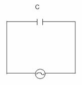
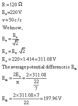
Q19. An electrical appliance of 120 Ω is connected to 220 V, 50 cycles a.c.? Calculate the average potential difference?
Solution
Q20. There are two capacitors A and B. Frequency of A is double than that of B but the capacitance is same. Find the ratio of there rectances.
Solution

Q21. The figure shows a series LCR circuit with L= 5.0 H, C = 80 μF, R = 40Ω connected to variable frequency 240 V source. Calculate
 (i) The angular frequency of the source which driver the circuit at resonance.
(ii) The current at the resonating frequency.
(iii) The rms potential drop across the capacitor at resonance.
(i) The angular frequency of the source which driver the circuit at resonance.
(ii) The current at the resonating frequency.
(iii) The rms potential drop across the capacitor at resonance.
(i) The angular frequency of the source which driver the circuit at resonance.
(ii) The current at the resonating frequency.
(iii) The rms potential drop across the capacitor at resonance.Solution
L = 5.0
C = 80μF
R = 40Ω
ε = 240 v.
(i) ω =  = angular frequency
=
= angular frequency
= =
= (ii) The current at the resonating frequency.
I =
(ii) The current at the resonating frequency.
I =  =
= 
 I at resanating frquency = 6 A
(iii) Vrms = Irms XC
XC =
I at resanating frquency = 6 A
(iii) Vrms = Irms XC
XC = 
 = 142.86 V
= angular frequency
=
=
(ii) The current at the resonating frequency.
I = =
I at resanating frquency = 6 A
(iii) Vrms = Irms XC
XC =
= 142.86 V
Q22. What is a parallel resonance circuit? Why is it called so?
Solution
Parallel resonant circuit is the one in which inductor and condenser is joined in parallel to a source of alternating e.m.f.
In a parallel resonant circuit the frequency of applied alternating e.m.f. is equal to the natural frequency of oscillation of circuit. Hence it is called parallel resonant circuit.

Q23. In a circuit a coil of resistance 100 Ω and inductance 0.1 H are connected across an ac voltage of frequency 100/2π Hz. What is the phase difference?
Solution
Given:
R=100 Ω
L=1 H
ν=100/2π Hz
Phase angle is given as,

Q24. A 100 Ω iron is connected to a 200 V supply with 50 Hz frequency. Find the rms value of current and the net power consumed over full cycle.
Solution
Given:


Comments
Post a Comment